To set the right mood in the cockpit, you naturally need proper lighting. This starts with the dome lights, continues with the console/floor lights, and includes the reading lights. In this post, we’ll be focusing on the console/floor lights.
These lights are located in the consoles beneath the side windows and illuminate the cockpit floor and the two sidebases. They are controlled by a switch on the MIP, which toggles between OFF, DIM, and BRT. In other words, there are two brightness levels.
To prevent both sides from losing lighting in the event of a DC power bus failure, the captain’s side is connected to the DC1 bus, while the first officer’s side is connected to the DC2 bus. The goal was therefore to design a circuit board for each cockpit side that replicates exactly this logic in the simulator and also allows the brightness for the BRT and DIM settings to be adjusted individually using a potentiometer on the circuit board.
The 12V supply for the circuit board is provided through a standard three-pin Phoenix Contact connector. The third pin carries an enable signal, which comes from another board (the power controller) that is linked to ProSim via an Arduino and Mobiflight. The enable line supplies 12V as soon as the DC1 or DC2 bus is powered.
A 555 timer circuit is used to generate a PWM signal, with the duty cycle determined by the setting of the onboard potentiometer. Using the switch on the MIP, it’s also possible to toggle between the potentiometer for DIM and the one for BRT. In the OFF position—or whenever the enable signal is not present—the 555 timer is switched off and the LEDs stay dark.
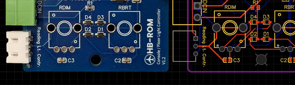
The board is currently in its fourth revision, V1.3. Designing it has taught me a great deal about electronics—especially how crucial clean signals are, where decoupling capacitors make sense, how important pull-up and pull-down resistors are, and how, without them, the human body can practically act as an antenna and introduce almost ghost-like interference.